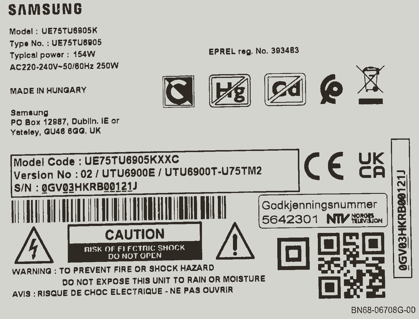
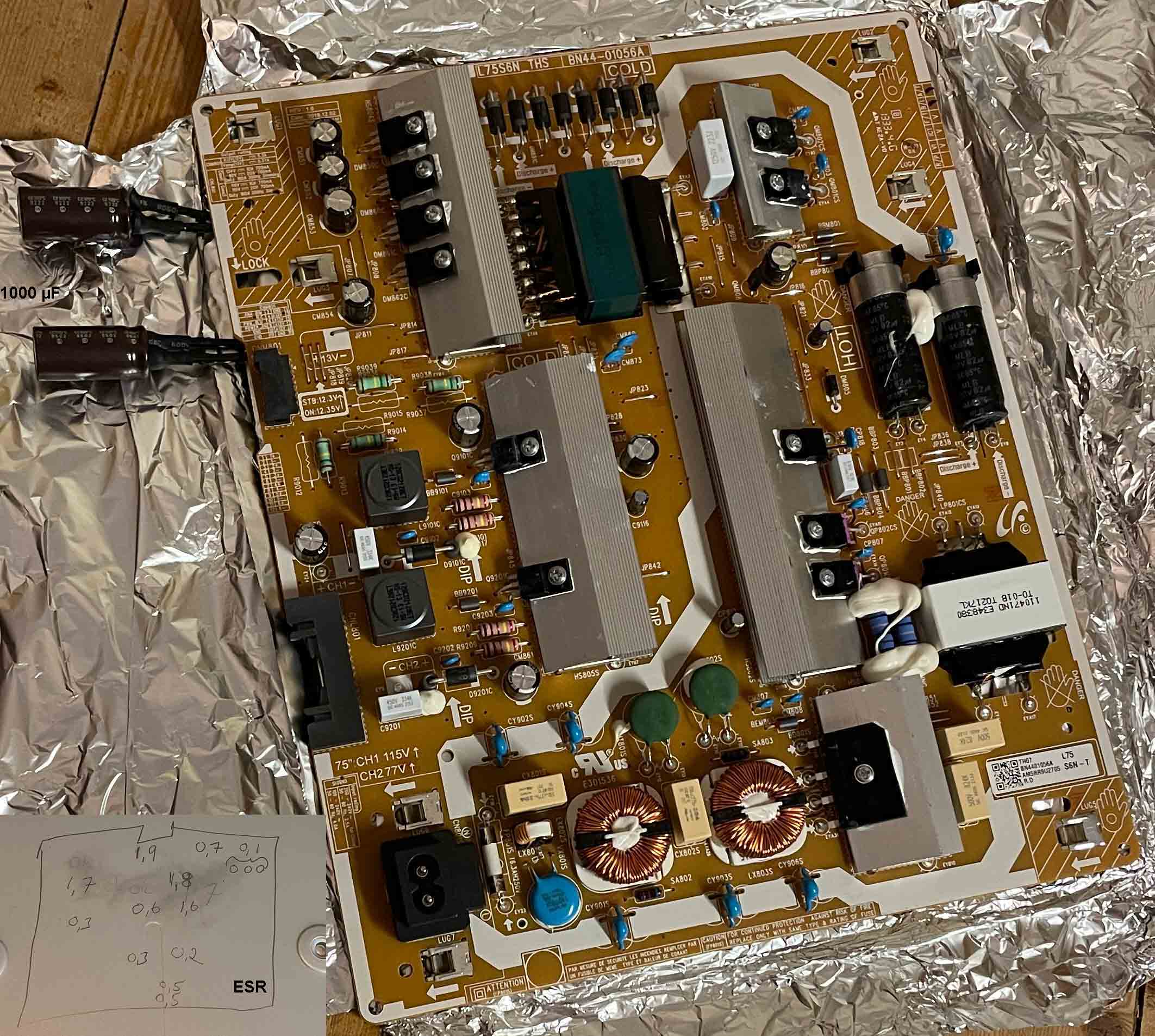
- Icke reparera själv en Samsung TV = livslängden endast fem!!!??? (5!!!???) år. Tolererar Samsung fel?! Nej. Fortfarande fel i moderkortet/CPU efter två nya kondensatorer för 13 VDC. Bakgrundsbelysningen lyser x sekunder och lysdioden blinkar rött x sekunder också men sedan blir allt mörkt och CPU ger hörbara låga och höga frekvenser och CPU blir ljummen :-( Lysdioden fast rött sken under tiden icke hörbart ljud men efter x sekunder hörbart ljud och lysdioden blinkar rött och sedan blir mörk under tiden hörbara låga och höga frekvenser.
Copyright ©
2016–2017, Texas Instruments Incorporated Product Folder Links: TPS564201
TPS564201 www.ti.com SLVSDJ7B–MAY 2016–REVISED AUGUST 2017 Feature Description
(continued) 7.3.4 Current Protection The output over-current limit (OCL) is
implemented using a cycle-by-cycle valley detect control circuit. The switch
current is monitored during the OFF state by measuring the low-side FET drain to
source voltage. This voltage is proportional to the switch current. To improve
accuracy, the voltage sensing is temperature compensated. During the on time of
the high-side FET switch, the switch current increases at a linear rate
determined by VIN, VOUT, the on-time and the output inductor value. During the
on time of the low-side FET switch, this current decreases linearly. The average
value of the switch current is the load current Iout. If the monitored current
is above the OCL level, the converter maintains low-side FET on and delays the
creation of a new set pulse, even the voltage feedback loop requires one, until
the current level becomes OCL level or lower. In subsequent switching cycles,
the on-time is set to a fixed value and the current is monitored in the same
manner. There are some important considerations for this type of over-current
protection. The load current is higher than the over-current threshold by one
half of the peak-to-peak inductor ripple current. Also, when the current is
being limited, the output voltage tends to fall as the demanded load current may
be higher than the current available from the converter. This may cause the
output voltage to fall. When the VFB voltage falls below the UVP threshold
voltage, the UVP comparator detects it. And then, the device shuts down after
the UVP delay time (typically 24 µs) and re-starts after the hiccup time
(typically 15.5 ms). When the over current condition is removed, the output
voltage returns to the regulated value.
Typical Application (continued) 8.2.1
Design Requirements Table 1 shows the design parameters for this application.
Table 1. Design Parameters PARAMETER EXAMPLE VALUE Input voltage range Output
voltage Transient response, 2-A load step Input ripple voltage Output ripple
voltage Output current rating 4.5 to 17 V 1.05 V ΔVout = ±5% 400 mV 30 mV
Operating frequency 4 A 560 kHz 8.2.2 Detailed Design Procedure
For
thisdesigntwoTDKC3216X5R0J226M22-µFoutputcapacitorsareused.ThetypicalESRis2mΩeach.
Thecal culated RMS current is 0.286A and each output capacitor is rated for 4A.
8.2.2.4 InputCapacitorSelection TheTPS564201 requires an input decoupling
capacitor andabulk capacitor is neededdependingon the application.TI
recommendsaceramiccapacitorover10µFfor thedecouplingcapacitor.Anadditional
0.1-µF capacitor(C3)frompin3togroundisoptional
toprovideadditionalhighfrequencyfiltering.Thecapacitorvoltage
ratingneedstobegreaterthanthemaximuminputvoltage.
www.ti.com SLVSDJ7B–MAY 2016–REVISED AUGUST 2017
8.2.2.5 Bootstrap Capacitor Selection A 0.1-µF ceramic capacitor must be
connected between the VBST to SW pin for proper operation. TI recommends to use
a ceramic capacitor.
From extern power supply ca 5,2 VDC to standby buck,
after coil, not to IC204 pin nr 3, no 13 VDC to motherboard, but current is now
1,4 to 1,6 A (7,3W), to motherboard it was only ca 0,7 A (0,8?) at ca 11-12 VDC
(7,7W): Blink pattern or error code: 22222 22222 21 22222 2222 222 2222 22 22222
2. 2 = 2 flash, 1 = 1 flash. This error code has similar structure as my car volvo 240, -90, but not so long, only 3 numbers, as an example: 1 2 3, there
nr 1 is one flash, nr 2 is two flash etc.