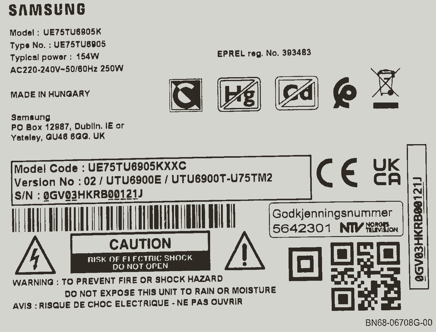
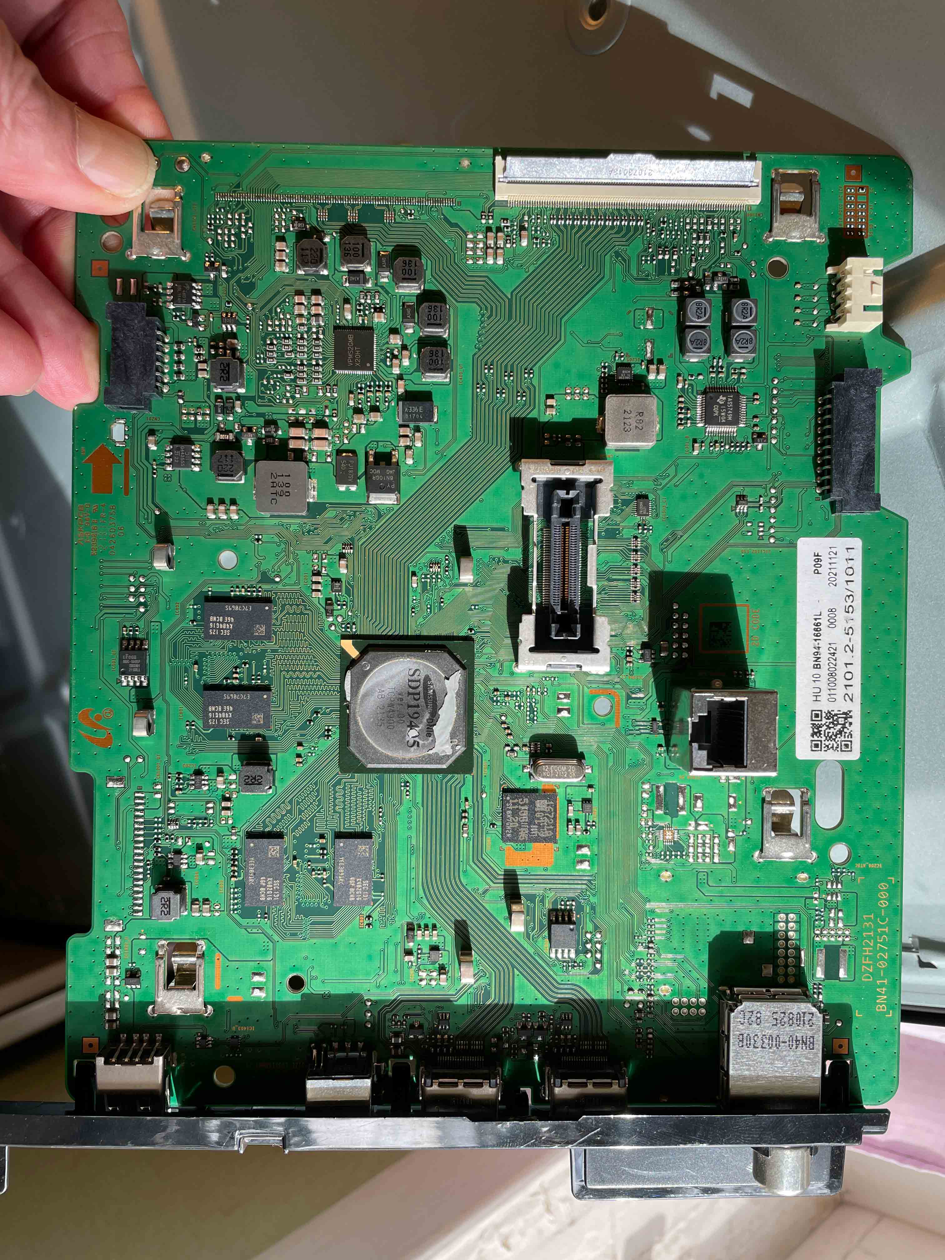
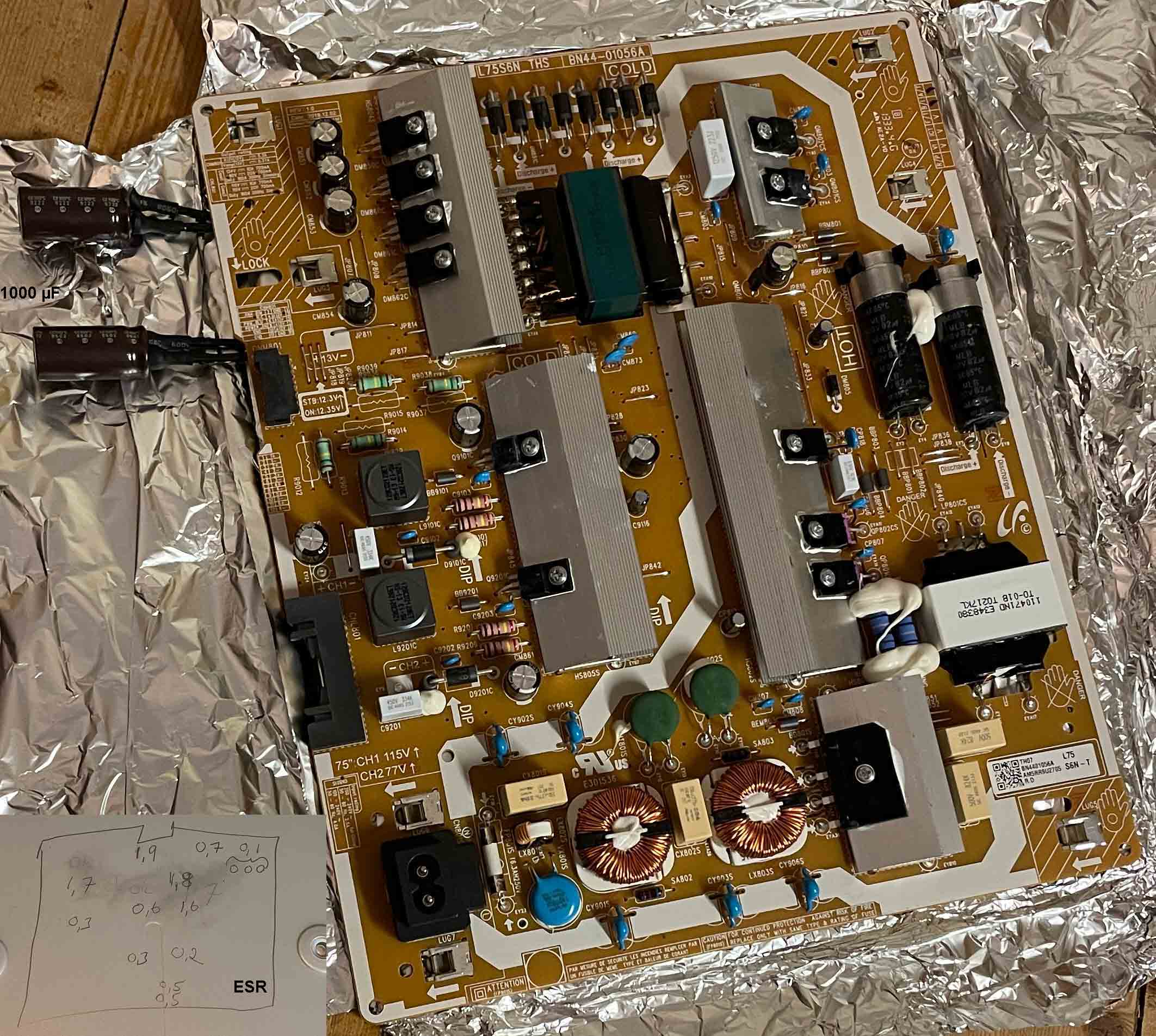
- Icke reparera själv en Samsung TV = livslängden endast fem!!!??? (5!!!???) år. Tolererar Samsung fel?! Nej. Fortfarande fel i moderkortet/CPU efter två nya kondensatorer för 13 VDC. Bakgrundsbelysningen lyser x sekunder och lysdioden blinkar rött x sekunder också men sedan blir allt mörkt och CPU ger hörbara låga och höga frekvenser och CPU blir ljummen :-( Lysdioden fast rött sken under tiden icke hörbart ljud men efter x sekunder hörbart ljud och lysdioden blinkar rött och sedan blir mörk under tiden hörbara låga och höga frekvenser.
Copyright © 2016–2017,
TPS564201 www.ti.com SLVSDJ7B–MAY 7.3.4 Current Protection The output over-current limit (OCL) is
implemented using a cycle-by-cycle valley detect control circuit. The switch
current is monitored during the OFF state by measuring the low-side FET drain to
source voltage. This voltage is proportional to the switch current. To improve
accuracy, the voltage sensing is temperature compensated. During the on time of
the high-side FET switch, the switch current increases at a linear rate
determined by VIN, VOUT, the on-time and the output inductor value. During the
on time of the low-side FET switch, this current decreases linearly. The average
value of the switch current is the load current Iout. If the monitored current
is above the OCL level, the converter maintains low-side FET on and delays the
creation of a new set pulse, even the voltage feedback loop requires one, until
the current level becomes OCL level or lower. In subsequent switching cycles,
the on-time is set to a fixed value and the current is monitored in the same
manner. There are some important considerations for this type of over-current
protection. The load current is higher than the over-current threshold by one
half of the peak-to-peak inductor ripple current. Also, when the current is
being limited, the output voltage tends to fall as the demanded load current may
be higher than the current available from the converter. This may cause the
output voltage to fall. When the VFB voltage falls below the UVP threshold
voltage, the UVP comparator detects it. And then, the device shuts down after
the UVP delay time (typically 24 µs) and re-starts after the hiccup time
(typically 15.5 ms). When the over current condition is removed, the output
voltage returns to the regulated value.
For
this design two TDKC3216X5R0J226M 22-µF output capacitors are used. The typical ESR is 2 mΩ
each. The culated RMS current is 0.286A and each output capacitor is rated for 4A.
8.2.2.4 Input Capacitor Selection TheTPS564201 requires an input decoupling
capacitor anda bulk capacitor is needed depending on the application. TI
recommends a ceramic capacitor over 10 µF for the decoupling capacitor. An additional
0.1-µF capacitor (C3)from pin3 to ground is optional
to provide additional highfrequency filtering. The capacitor voltage
rating needs to begreater than the maximum input voltage.
The capacitorvalue and ESR determines the amount of output voltage ripple. TheTPS564201
is intended for use with ceramic or other
low ESR capacitors. Recommended values range from 20 µF to 68 µF.
www.ti.com SLVSDJ7B–MAY 2016–REVISED AUGUST 2017
8.2.2.5 Bootstrap Capacitor Selection A 0.1-µF ceramic capacitor must be
connected between the VBST to SW pin for proper operation. TI recommends to use
a ceramic capacitor.
From extern power supply ca 5,2 VDC to standby buck, after coil, not to IC204 pin nr 3, no 13 VDC to motherboard, but current is now 1,4 to 1,6 A (7,3W), to motherboard it was only ca 0,7 A (0,8?) at ca 11-12 VDC (7,7W):
Blink pattern or error code: 22222 22222 21 22222 2222 222 2222 22 22222 2. 2 = 2 flash, 1 = 1 flash.
Blink pattern or error code: blink–blink, short pause, blink–blink, short pause, blink–blink, short pause, blink–blink, short pause, blink–blink, long pause, blink–blink, short pause, blink–blink, short pause, blink–blink, short pause, blink–blink, short pause, blink–blink, long pause, blink–blink, short pause, blink, long pause, blink–blink, short pause, blink–blink, short pause, blink–blink, short pause, blink–blink, short pause, blink–blink, long pause, blink–blink, short pause, blink–blink, short pause, blink–blink, short pause, blink–blink, long pause, blink–blink, short pause, blink–blink, short pause, blink–blink, long pause, blink–blink, short pause, blink–blink, short pause, blink–blink, short pause, blink–blink, long pause, blink–blink, short pause, blink–blink, long pause, blink–blink, short pause, blink–blink, short pause, blink–blink, short pause, blink–blink, short pause, blink–blink, long pause, blink–blink. I hope I have had count right but the video is right...
This error code has similar structure as my car volvo 240, -90, but not so long, only 3 numbers, as an example: 1 2 3, there nr 1 is one flash, nr 2 is two flash etc.
Samsung TV Blink Codes (Detailed Guide!) - The Tech Gorilla
| Blink Code | Likely Cause | Difficulty | Best Fix |
|---|---|---|---|
| 1 Blink/sec | Power supply issue | Easy | Check power cable and outlet |
| 2 Blinks/sec | Software glitch, HDMI, or LCD panel | Easy–Moderate | Power cycle or reset remote |
| 3 Blinks/sec | Faulty backlight / LED strip | Advanced | Replace damaged LED strips |
| 4 Blinks/sec | Mainboard / T-CON board failure | Advanced | Inspect and replace capacitor |
| 5 Blinks/sec | Mainboard, overheating, or backlight | Moderate–Advanced | Cool down TV or button reset |
| 6 Blinks/sec | Power fluctuation or mainboard | Moderate–Advanced | Power cycle and inspect components |
https://copilot.microsoft.com/: 2‑blink protection loop → PSU‑instability / power‑logic fault / Tizen boot‑reset loop. • Power supply rail instability (PSU cannot hand over stable voltage) • Protection relay reset loop (TV tries to start → fails → resets) • Capacitor saturation / voltage leak on the 13 V rail • Instant On snapshot corruption (Tizen fails to load RAM image) • HDMI over current handshake fault (bad cable or device).
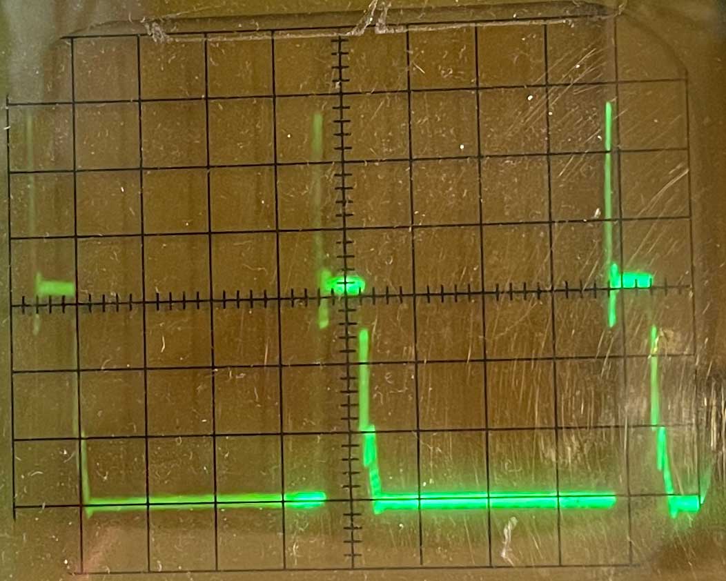
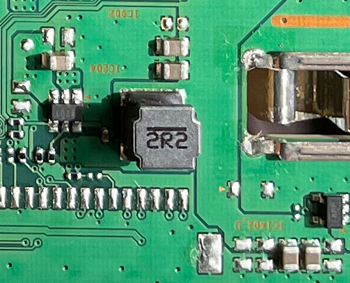
Samsung_TV_buck_4201_5,2V_20mV_div_0,5mS_div_Output_ripple_voltage.jpg The rail voltage: 5,2 V, 20mV/div, 0,5mS/div. Probed at the coil (2R2) but from the rail to chassi. Ripple: 70 to 90 mV. IC204 (4201). Samsung_TV_UE75TU6905KXXC: TPS564201: Is Output Voltage Ripple to high? Why is the ripple so high?
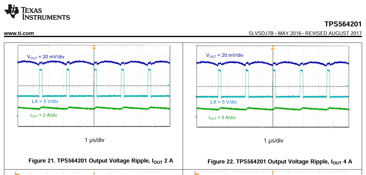
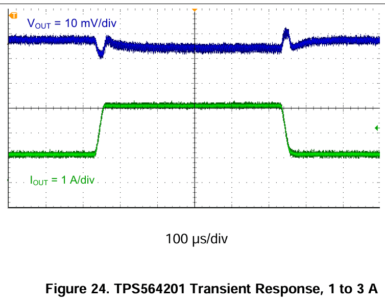
Samsung_TV_TI_TPS564201OutputVoltageRipple.gif Samsung_TV_UE75TU6905KXXC: TPS564201: Is Output Voltage Ripple to high? One picture is from the TV, the another is from TI. If, yes, why is the ripple to high?
Samsung_TV_extern_power5,2V_50mV_div_1mS_div_RailRipple.jpg 50 mV/div, 1 mS/div. The rail 5,2 VDC is connected to: SoC / SDP19405 and USB (5V 0,5A) and maybe HDMI IN 1 and HDMI IN 2 (eARC) and DIGITAL AUDIO UT (OPTICAL) and ANT IN etc? Why is SDP19405 blinking 2 times and do not start? Has Tizen problem to load RAM image? no, POST/BOOT do not load/ok and the root cause is almost always a power‑rail instability, source: copilot.microsoft.com/. After the image has bee loaded, all another rails start up and the screen is starting also? I connected now from an extern power (Oltronix power supply B32_30R) to 5,2 V, current limit ca 3 A, rail and the ripple is now much higher: 280 mV but the copper trace wire for the 5,2 V is long from the power supply unit and only 0,75 mm2 and the buck 4201 is not in service any longer and compensating for the rippel, maybe, is that why the ripple is higher? no buck that is compensating or reducing the ripple? is the problem high ESR? It is still that beeping (250Hz?/4mS?) sound. Maybe no problem with the buck 4201 if the sound is still there. Maybe is something oscillating? coil? capacitor? SDP19405? The SDP19405 is only little warm.
Samsung_TV_extern_power5,2V_50mV_div_1mS_div_RailRipple1000microFarad.mp4 The RailRipple structure has changed with 1000 micro Farad over 5,2 V. Still, the TV can not start after the extra capacitor. Ca 335 mV... is the oscilloscope ok?!
The transients is starting after x seconds when the extern tension 5,2 V is connected to the rail. Directly no transient when I connect the wire 5,2 V to the rail but after x seconds the transients slowly rising to ca 335 mV. What unit is starting slowly?
TPS564201: 8.2.1 Design Requirements Table 1 shows the design parameters for this application. Output voltage: 1,05 V Transient response, 2-A load step: ΔVout = ±5%. Hm... must you have a big capacitor? Not "Recommended values range from 20 µF to 68 µF", maybe 5 x 100 µF?
Samsung_TV_Figure24.TPS564201TransientResponse,1to3A.gif
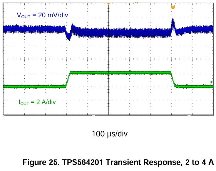
Samsung TV Figure 25. TPS564201 Transient Response, 2 to 4 A.gif
Is Samsung TV buck "a stable circuit" / "the system phase margin" / "insufficient phase margin" / "ensure enough phase margin and system stability"? for the buck 4201/D-CAP2? Why are the inductor 2,2 µH? Texas instruments recommend 3,3 µH for OUTPUT VOLTAGE(V)5 R1(kΩ)54,9 R2(kΩ)10,0 L1(µH)min3,3 typ3,3 max4,7 C8+C9(µF)20to68µF. The inductor 2,2 µH gives 3,3 V. Is 3,3 V ok? But USB etc. must have 5 V, maybe... but the frequency (250?Hz) is low at this actual problem, not 560 kHz... What unit has ca 250 Hz?
Stability depends strongly on output capacitor value and ESR. Source: Microsoft Copilot: Din AI-assistent / Stability Analysis and Design of D-CAP2 and D-CAP3 Converter – Part 1
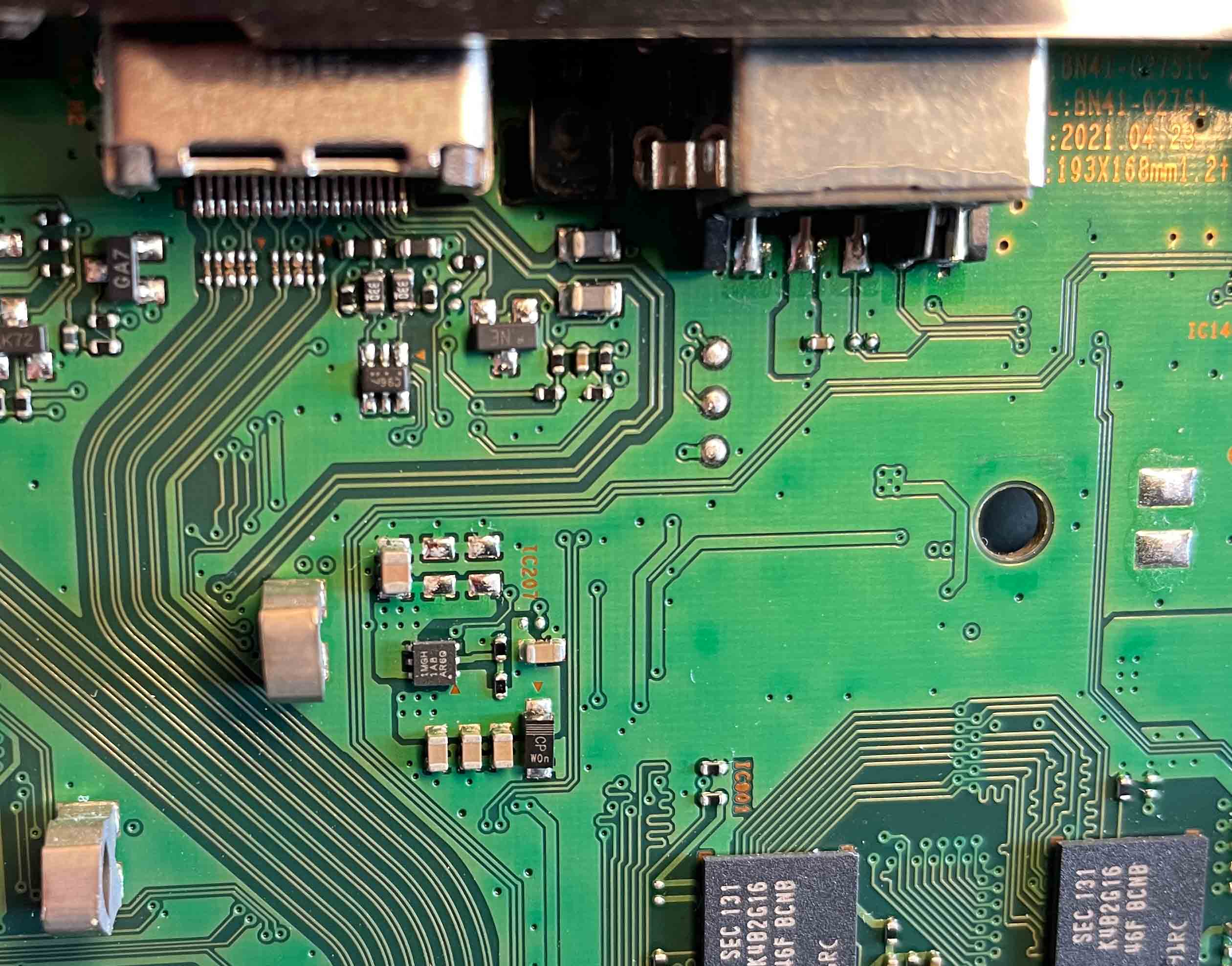
The unit IC 6-pin 1MGH 1A8 AR6Q has ca 250 Hz because of low resistance between the rail 3,3 V and GND. The tension (voltage) is only ca 2,x V. IC 1MGH 1A8 AR6Q from 5,2 V to 3,3 V.
"--- However, after further investigating, this chip is part of a series of Intel Atom/Celeron/BayTrail chips that have bad I/O designs that cause them to short out over time with use (this is a known errata, I remember reading about it but my board seemed to be fine then). I am not sure which I/Os are affected, I guess, good luck asking for Intel for more information. This could be why our boards died. ---" Source: https://www.vogons.org/viewtopic.php?t=84815 2022-01-15 21.05 the3dfxdude Oldbie
Injection of tension / current to the rail 3,3 V and GND, IC 1MGH 1A8 AR6Q, from extern power supply max 7 W / x,x V = 3,5 A, constant current (CC). If I do not find any problem I would BURN UP THE CRAP with 32 A and 30 V = 1 kW!!!
SDP19405: On the heat sink the room temperature is 21,1 °C. On the heat sink the temperature is 21,6 °C with 0,25 A and 1,4 V. On the heat sink the temperature is 22,4 °C with 0,41 A and 1,4 V. On the heat sink the temperature is 24,3 °C with 0,56 A and 1,8 V. On the heat sink the temperature is 25,2 °C with 0,6 A and 1,9 V. On the heat sink the temperature is 26,9 °C with 0,7 A and 2,1 V. On the heat sink the temperature is 28,4 °C with 0,95 A and 2,4 V. On the heat sink the temperature is 30 °C with 1,08 A and 2,55 V. On the heat sink the temperature is 32 °C with 1,27 A and 2,7 V. On the heat sink the temperature is 34 °C with 1,34 A and 2,7 V. The rail 3,3 V or x,x V or what?
"--- Bidirectional I/O ports have historically been another source of system failures. When a processor’s I/O port and that of a supporting peripheral, such as memory or a data converter, do not share the same supply, the potential for latch-up exists. Bus contention occurs when multiple devices simultaneously attempt to control a bidirectional bus during power-up, which can affect I/O reliability. ---" Sourse: Powering today´s multi-rail FPGAs and DSPs, Part 1 Good power-supply design techniques, s.10.
SDP19405: Extern power supply to the rail 3,3 V: On the heat sink the room temperature is 20,3 °C. On the heat sink the temperature is 25 °C with 0,63 A and 2,2 V. On the heat sink the temperature is 35,4 °C with 1,16 A and >=3,1 V -> led steady red light after many blink-blink.
On the heat sink the temperature is 39,6 °C with 1,34 A and 3,3 V = 4,4 W: blink–blink, short pause, blink–blink, short pause, blink–blink, short pause, blink–blink, short pause, blink–blink, long pause, blink–blink, short pause, blink–blink, short pause, blink–blink, short pause, blink–blink, short pause, blink–blink, long pause, blink–blink, short pause, blink, blink, short pause, blink–blink, short pause, blink–blink, short pause, blink–blink, LED steady red light long time x min., blink–blink, short pause, blink–blink, short pause, blink–blink, short pause, blink–blink, short pause, blink–blink, long pause, blink–blink, short pause, blink–blink, short pause, blink–blink, short pause, blink–blink, short pause, blink–blink, long pause, blink–blink, short pause, blink, blink, short pause, blink–blink, short pause, blink–blink, short pause, blink–blink, LED steady red light long time x min., etc.
Interfer the IC 6-pin 1MGH 1A8 AR6Q with transients in to SoC or has the unit problem with overcurrent? Extern power supply give the blink-blink as described above text and a "good behavior", maybe.
The IC 6-pin 1MGH 1A8 AR6Q is now removed from the rail 3,3 V but sometimes the current is ca 2,6 A and only 2,x V from the extern power supply in CC but the temperature increases fast... 3,3 V and CV and current x A gives 50-60 °C, I do not remember...
If the current is "normal" from the extern PSU and the original PSU is in service also nothing happends, no blinking / no steady light but the temperature increases fast... and if I remove the extern PSU 3,3 V the backlight lit up as a blink (0,1? sec).
I give up!!! Can you fix it?
New motherboard? new SoC? but what warranty has that?
The next stop for this crap is "Risslan recycling center Luleå".
Problem med SoC SDP19405. Ibland låg ström eller ibland hög ström för 3,3 V. Lysdioden blinkar om spänningen är >=3,1 V OCH om strömmen/spänningen ökar från 0,xA/2,xV till xA/3,3V under tiden x minuter. Om ström/spänning ökar x sekunder (x mS?) ökar värmen till xx °C och LED inte blinkar.